Piping And Instrumentation Drawings
The author offers a proven systemic approach to present the concepts of pid development which previously were deemed to be graspable only during practicing and not through training. You will learn how to read pid and pefs with the help of the actual plant drawing.
 Practical Process Plant Layout And Piping Design
Piping and instrumentation diagram also called pid is a diagram used to show a graphical display of a complete system.

Piping and instrumentation drawings. It includes all piping instruments valves and equipment that the system consist of. The title block of a drawing usually located on the bottom or lower right hand. A piping and instrumentation diagram pid is a drawing in the process industry.
In the process industry a standard set of symbols is used to prepare drawings of processes. An essential guide for developing and interpreting piping and instrumentation drawings. Piping design estimating purchasing used to evaluate construction progress training basis for operational personnel.
All drawings can be classified as either. Valves are used to control the direction flow rate and pressure of fluids. Pid is more complex than of pfd and includes lots of details.
Piping and instrumentation diagram development is an important resource that offers the fundamental information needed for designers of process plants as well as a guide for other interested professionals. A piping and instrumentation diagram pid is defined by the institute of instrumentation and control as follows. A diagram which shows the interconnection of process equipment and the instrumentation used to control the process.
A control valve may serve any. A generic engineering drawing can be divided into. Piping and instrumentation drawing pid tutorials part 1 anatomy of a drawing.
A pid shows all piping including the physical sequence of branches reducers valves equipment instrumentation and control interlocks. Link to download this pid is given at the end of the page. Piping and instrument drawings pids electrical single lines and schematics electronic diagrams and schematics logic diagrams and prints and.
The piping and instrumentation diagram is also known as the process engineering flow scheme which is pefs. Piping and instrumentation drawing pid tutorials part 3 valve symbols. Some valves are provided with actuators to allow remote operation.
Fabrication construction and architectural drawings.
 Piping And Instrumentation Diagram Wikipedia
 How To Read A Piping And Instrumentation Drawing Video Valve
The Three Types Of Process Diagrams Lowflow Valve Fractional
Piping And Instrumentation Diagram Symbols
 Piping And Instrumentation Diagrams Tutorials Iv Learning
 Piping And Instrumentation Diagrams Youtube
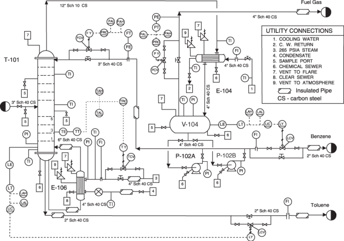 Draft Any Piping Instrumentation Diagram For You By Ayodaygee
Piping And Instrumentation Diagram Pid For 3kwe Solar Orc
 Piping And Instrumentation Diagram P Id Showing Components
Ten Essential Components Of Piping And Instrumentation Diagrams
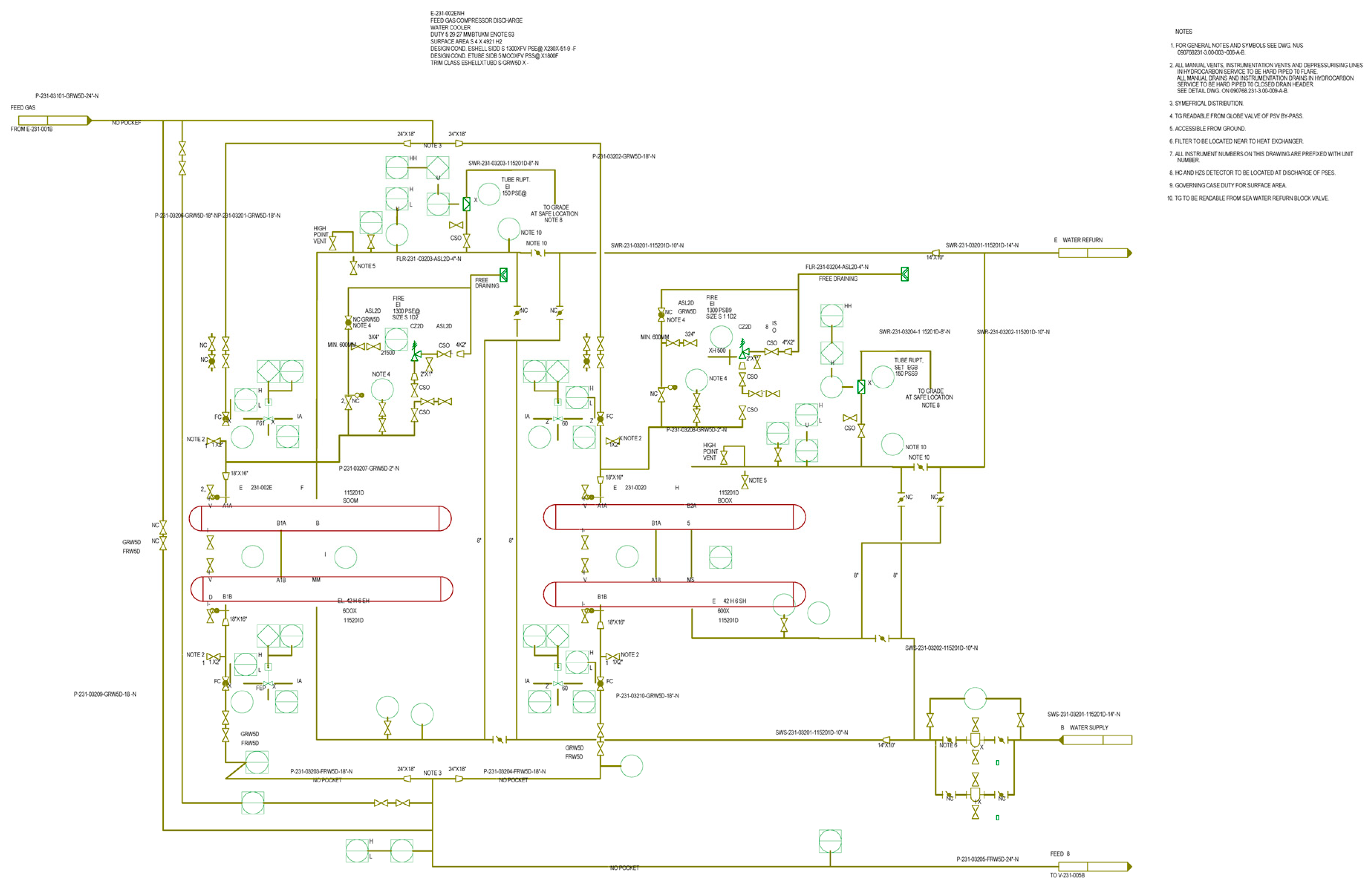 Energies Free Full Text A Digitization And Conversion Tool For
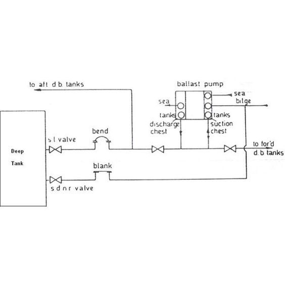 Piping Instrumentation Drawings Tejjy Inc Usa
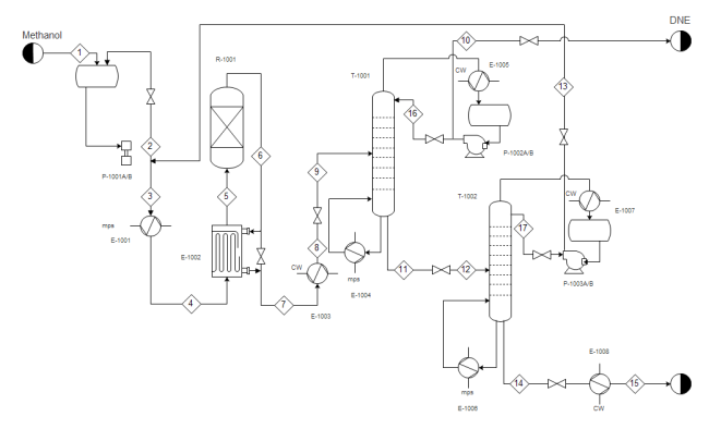 How To Read Piping And Instrumentation Diagram
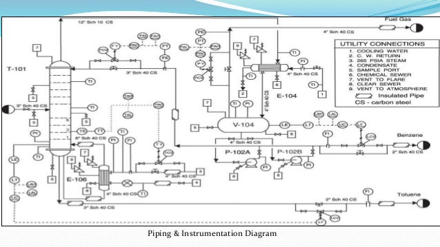 Piping And Insruementaion Diagrams
 Piping And Instrumentation Diagram P Id Of A Multi Purpose Heat
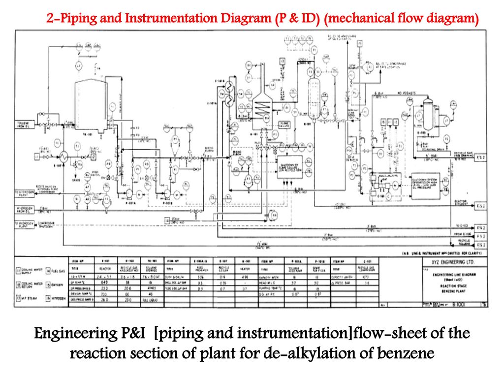 346bc7 Piping And Instrumentation Diagram Manual Wiring Resources
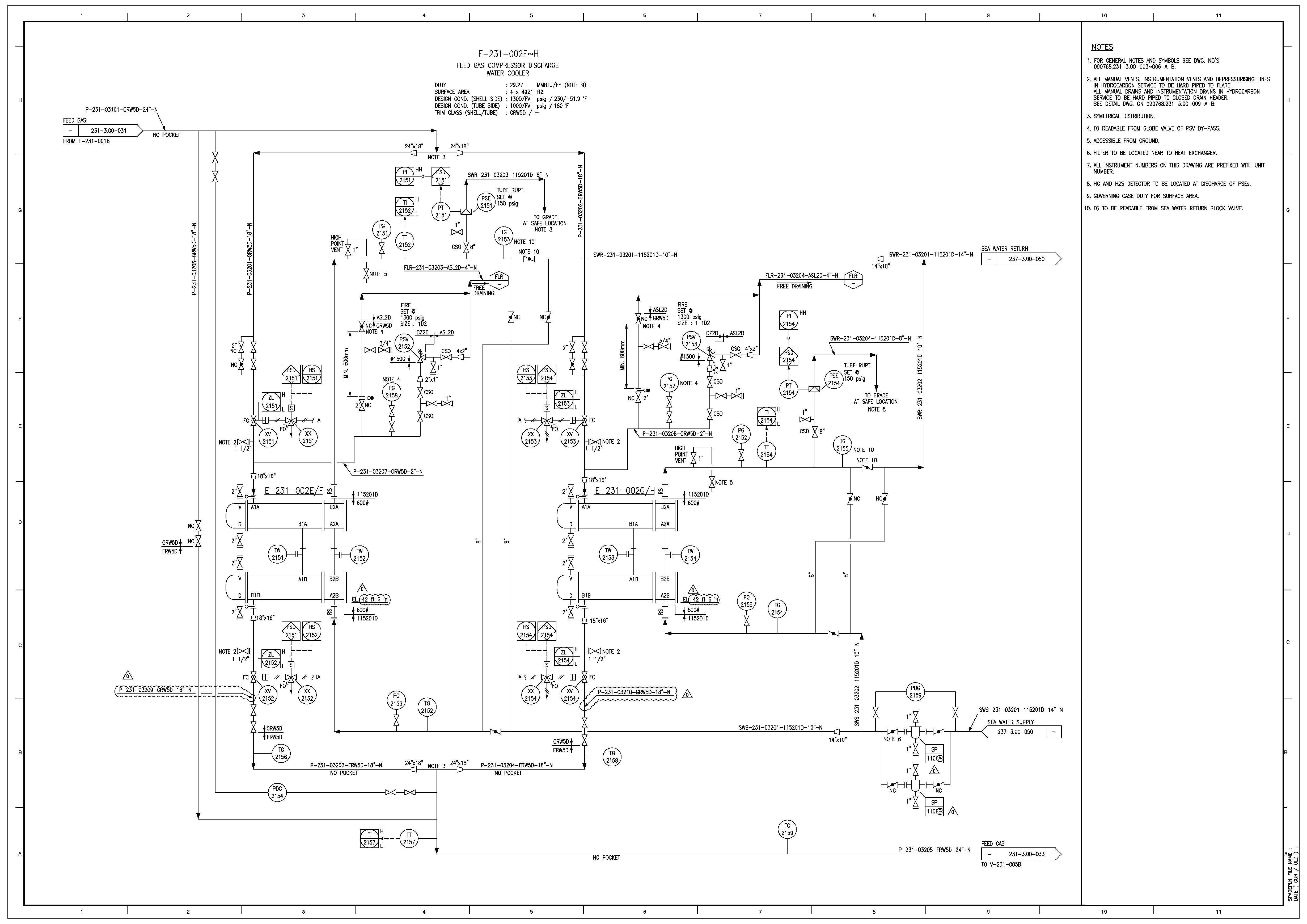 Energies Free Full Text A Digitization And Conversion Tool For
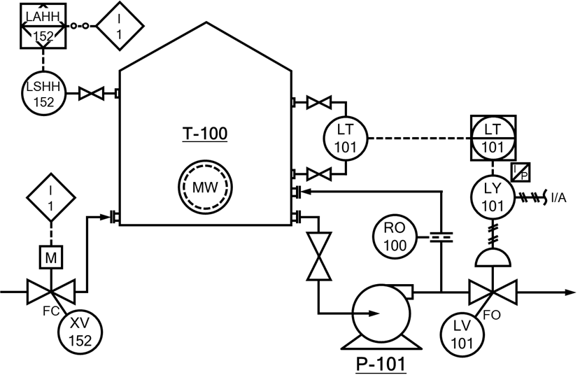 P Id Piping And Instrumentation Diagram And Engineering Drawings
Boiler Piping And Instrumentation Diagram
 Pipe Instrument Diagram Of Reactor Process Download Scientific
 Piping And Instrumentation Diagram In Kodambakkam Chennai Mechci
 Simplified Drawings Piping And Instrumentation Drawings P Ids
 How To Read Piping And Instrumentation Diagram P Id Youtube
0 Response to "Piping And Instrumentation Drawings"
Post a Comment